
Router Thermal Paste Selection for an Eight Year Life Without a Fan
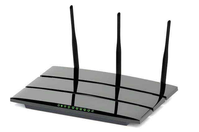
Thermal Paste in a Router: A Thin Joint That Must Last Eight Years Without a Fan
An access point drawing 18 W in a sealed plastic enclosure, standing in a 45 °C cabinet for eight years, is a different problem from a laptop that bursts for thirty seconds. There is no fan to raise, no service visit, no heatsink added later. Heat leaves through the same plastic wall for roughly 70,000 hours, and the radio front end sits centimetres from the processor producing most of it. That is why router thermal management is a materials question before it is an airflow question.
Where the watts actually go
A mainstream Wi-Fi 6 or 7 router spreads its budget across four to six parts, each with a different flux. Treating the box as one 18 W source is the first simplification that produces a wrong joint specification in router thermal management: the smallest parts carry the highest density, not the processor.
| Path segment | Typical flux | What sits there | Why it matters |
|---|---|---|---|
| SoC die to shield can | 3–6 W/cm2 | 10 x 10 mm die at 5 W | Thin joint possible, low clamp |
| Front-end die to can | 6–9 W/cm2 | 1.5–2 W on a 5 x 5 mm die | Worst flux in the box |
| Can to aluminium plate | 1–2 W/cm2 | Stamped can, 0.2 mm | Can warps, gap varies |
| Plate to plastic housing | 0.3–0.6 W/cm2 | Air gap or thin pad | Spreading, not conduction |
| Housing to room air | Natural convection | Vertical wall, no fan | The real limit |
Two conclusions follow. The joint that matters most is not under the processor but under the front-end modules, where flux is highest and clamp load is lowest. And the last two segments dominate the total rise, so a thermal paste that saves 0.4 K at the die must not cost anything on the housing side.
Why a 0.5 mm pad is the default, and where it stops being right
Most routers ship with a gap pad because the stack is loose: a stamped can, a plastic bracket, a screw every 20 mm, tolerances adding to half a millimetre. A pad absorbs that, and at 2 W/cm2 a 0.5 mm pad costs about 2 K, which the design can afford. The problem appears when the same pad is carried over to a joint whose real gap is 0.1 mm and whose flux is 6 W/cm2, where no thermal paste is needed to beat it by a factor of ten.
| Option | Bond line | Rise at 5 W/cm2 | Router verdict |
|---|---|---|---|
| Thermal paste, 0.03 °C·cm2/W | 10–20 µm | 0.15 K | Best where a screw clamps the can |
| Thermal paste, 0.080 °C·cm2/W | 20–40 µm | 0.4 K | Forgiving of slight can warp |
| Thermal paste, 0.201 °C·cm2/W | 30–60 µm | 1.0 K | Fine on the SoC, not on the FEM |
| Gap pad, 0.5 mm at 5 W/m·K | 500 µm | 5 K | Correct only for real gaps |
| Gap pad, 1.0 mm at 3 W/m·K | 1,000 µm | 16.7 K | Never under a 6 W/cm2 part |
Five things a datasheet does not describe
Eight years is a creep test, not a viscosity test. A router sits at 60–75 °C at the joint and cycles gently. The failure mode is slow loss of contact area at the edge, not fast pump-out. A thermal paste picked for the best day-one impedance on a soft base can be dry in year three; a slightly stiffer grade at 0.080 °C·cm2/W is still there in year eight.
Volatiles reach the antenna. Silicone-based pastes release low-molecular siloxane, and in a sealed plastic box that vapour has nowhere to go but onto the antenna elements and the matching network. The result is not a thermal failure but an RF one: a fraction of a dB of insertion loss and a slow VSWR drift nobody attributes to the thermal interface material, which makes it the most under-tested interaction in router thermal management.
Wall mounting changes the joint. Many access points hang vertically on a wall or pole, and a vertical joint at 70 °C drains a low-viscosity paste over years, leaving a dry region at the top of the die. Either keep the joint horizontal in the layout, or accept a stiffer grade and a thicker bond line.
Stamped cans are not flat. A 0.2 mm shield can warp by 0.1–0.2 mm across a 40 mm face, and no thermal paste bridges that. The answer is a screw pattern that flattens the can locally, or a pad where the warp is largest — not a thicker paste layer everywhere.
Service access is real. Routers return for RF tuning, firmware recovery and refurbishment, and a non-curing thermal paste lets a can be lifted and re-applied. A cured or phase-changed film does not, and a pad compressed twice reads worse than a fresh print.
Selecting the grade for a sealed box
The TSAD Series from TOUSEN is a solvent-free, non-curing thixotropic gray paste covering 1.2–6.5 W/m·K, with measured impedance of 0.03 to 0.201 °C·cm2/W at 30 psi, specific gravity 2.5–2.9 g/cm3 and a 12-month shelf life. In a router the choice of a thermal interface material is narrower than in a phone or a server: pick the grade whose bond line survives eight years at 70 °C, then confirm the volatile fraction is low enough for the radio.
| Grade | W/m·K | Impedance @ 30 psi (°C·cm2/W) | Density (g/cm3) | Typical router position |
|---|---|---|---|---|
| TSAD60 | 1.2 | 0.201 | 2.5 | Low-flux PHY and DDR under a can |
| TSAD66 | 3.5 | 0.080 | 2.7 | Can to plate, long-life joints |
| TSAD66-P | 4.0 | 0.070 | 2.6 | Cans with slight warp, thicker print |
| TSAD83 PLUS | 5.2 | 0.050 | 2.6 | Mainstream Wi-Fi 6/7 processor |
| TSAD88 PLUS | 5.2 | 0.030 | 2.9 | Front-end modules at 6–9 W/cm2 |
| TSAD90 | 6.5 | 0.030 | 2.7 | High-power FEM and 10G PHY |
| TSAD100 | 6.5 | 0.030 | 2.8 | Fanless enterprise AP, large plate |
Dose by mass, because the joint is 10 to 20 µm
At 2.7 g/cm3 a 15 µm joint needs 4 mg per cm2, so a 40 x 40 mm can takes about 65 mg. A 30 percent over-dose is then 0.6 K over the whole part, and at 8 W/cm2 that separates a compliant front-end module from a marginal one. A syringe with a defined shot size beats an operator judging a cross pattern by eye.
At that scale the thermal interface material is being dosed in fractions of a milligram per part: for a 5 x 5 mm front-end die the shot is under 1 mg, which no manual dispenser holds repeatably; stencil printing at 0.1 mm with 80 percent coverage is the practical route, and it keeps the paste off the matching components beside the die.
Clamp load decides whether paste is allowed at all
A thermal paste joint needs pressure, and pressure is what most router brackets lack. With M2.5 screws at 0.4–0.6 N·m on a 40 mm can the average is 3 to 8 psi, enough for a 20 µm joint but not for 10 µm. Where a can is held by clips only, centre pressure may fall below 1 psi and a 0.5 mm low-modulus pad outperforms any paste. That is not a contradiction; it is the design boundary.
Where paste is the wrong part
Between the aluminium plate and the plastic housing, around the DDR and switch fabric under a wide can, and at the housing interface of a wall-mounted unit, no thermal interface material in paste form closes the gap, and a pad is correct: those gaps are 0.3 to 1.5 mm and exist to absorb tolerance. Thermal paste there is squeezed into the void without closing the gap, and adds volatile mass inside a sealed box for no benefit.
Qualification that matches an eight-year life
Router thermal management is judged on units nobody will open, so the plan must compress time rather than measure a first article. Run the board at rated load in a 45 °C chamber for 1,000 hours, logging temperature at the processor, the hottest FEM and the plate edge, then add 200 cycles from -10 °C to 60 °C, 500 hours at 70 °C and 85 % RH, an oil separation test at 150 °C and an outgassing check by weight loss. Then measure RF insertion loss and VSWR on the same sample before and after: if the antenna match has moved, the paste is part of the cause. Finish with drop and vibration on the packed unit.
Assembly rules that survive a factory audit
- Clean the can and plate with isopropyl alcohol and verify visually: residue of thermal paste under 15 µm is a hot spot no spreader can average out.
- Torque the can screws diagonally in two passes and never re-torque after the joint settles.
- Use one dated syringe per model or a printed deposit; topping up a used syringe changes solids content and volatiles.
- Never reuse paste lifted from a can, and never mix two grades to chase a number.
- Store cartridges closed below 30 °C away from flame; the product is non-hazardous, but an open cartridge loses solvent balance within months, and that loss ends up on the antenna.
Conclusion
In router thermal management the thermal paste joint is thin in dimension and large in consequence: 15 µm of thermal paste instead of a 1 mm pad is worth 16 K on a front-end module, which is the difference between a warm case and a radio that throttles. The discipline is to treat the box as five segments, to put paste only where a screw supplies pressure, to choose the grade by eight-year stability rather than first-day impedance, and to treat siloxane volatility as an RF parameter. A sealed fanless enclosure then holds its temperatures for a decade without a service visit.
Impedance data, grade table and packaging options for the thermal paste grades described here are published on the TSAD Series thermal paste product page, and samples for stencil trials on a shield can can be requested there.
Thermal Paste Selection for Server Thermal Management
Related Article