
Engineering Guide to Silicone Thermal Pads and Gap Filler Pads
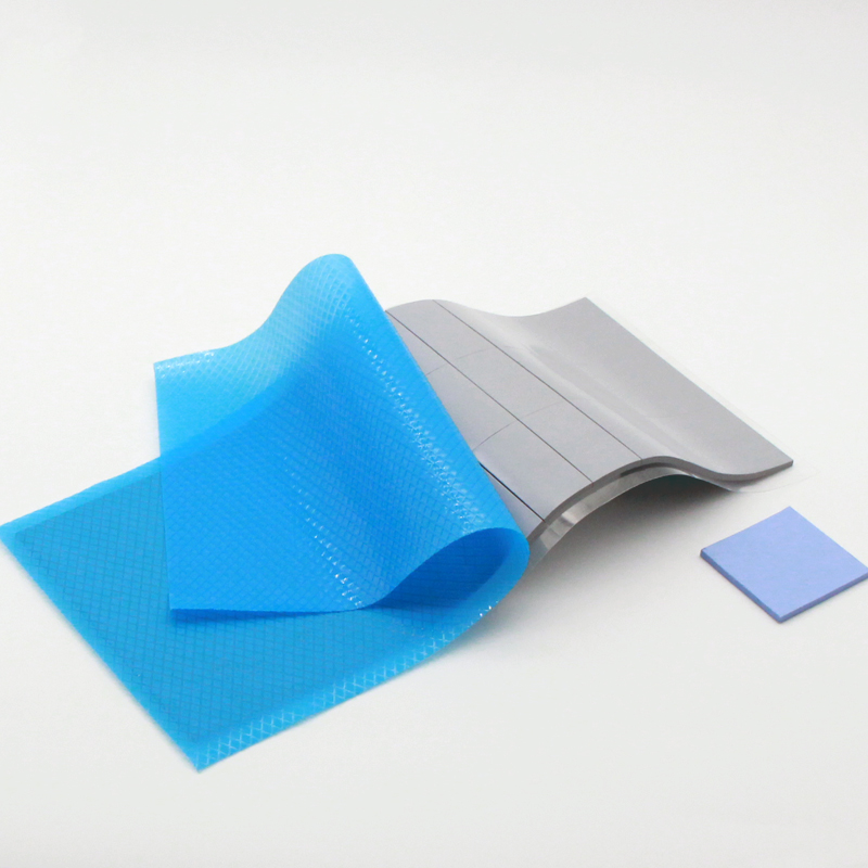
Engineering Checklist for Thermal Silicone Sheets: Hardness, Die-Cut, Liners, Tear Tabs & De-tack
Overview: Thermal silicone sheets (thermal pads / silicone thermal pads) are a mature TIM technology. Yet in mass production, detailed factors—hardness matching, die-cut features, release liners, tear-tab design and de-tack processing—regularly determine yield and thermal performance. This engineering-focused article compiles practical checks and TOUSEN field cases to guide production-ready decisions.
Although thermal pads and thermal silicone sheets are widely used because of handling convenience, insufficient front-end validation between mechanical, thermal and manufacturing teams causes repeated production issues. Below are five core engineering areas that require joint design verification.
1. Hardness matching — a structural decision
Hardness must be treated as a system parameter. A pad that's too hard can produce reaction forces that lift or bend PCBs; too soft and thermal conduction under low clamp pressure suffers.
- Specify target compression ratio (e.g., 20–40%) instead of Shore alone.
- Compute reaction forces and bending moments for sensitive assemblies (BGA, long traces).
- Require supplier data for compression set and rebound.
2. Die-cut geometry — holes, frames and minimum feature size
Design rules for die-cut parts are necessary: narrow frames (<1 mm) and small perforations are prone to tearing and handling problems.
- Avoid frame widths <1.0 mm unless process validated.
- Correlate thickness/hardness with minimum feature sizes.
- Prototype with intended cutting method (die cut vs laser) and run peel/placement durability tests.
3. Release liners and handling films — balance removability and protection
Select liners based on assembly method, operator ergonomics and placement automation. Too-high peel force impedes handling; too-low peel force leads to premature delamination.
- Measure liner peel force across operating temperatures.
- If customer-supplied liners are used, validate batch consistency.
4. Tear-tab design — small cost, large impact
Tear tabs significantly improve throughput and first-pass yield. Position, size and orientation must avoid interference with connectors and clips.
- Standard: 4–8 mm grab width, placed at unobstructed edges.
- Test ergonomics and automation gripper compatibility.
5. De-tack processes — don't trade handling for thermal loss
Many de-tack methods reduce tack but damage surface filler distribution, increasing interface thermal resistance. Validate any de-tack option with Rth testing under representative clamp pressure.
- Perform thermal Rth tests before production sign-off.
- Consider non-destructive de-tack options that preserve filler network.
Production readiness checklist (supplier–customer sign-off)
- Mechanical stack review: thickness, compression ratio, reaction forces.
- Die-cut validation with intended tooling and edge integrity checks.
- Release liner peel tests and robotic placement mockups.
- Tear-tab ergonomics and gripper tests.
- Thermal verification: Rth under expected clamp pressure and thermal cycling.
- Long-term stability: compression set and aging tests.
Conclusion — early collaboration reduces production risk
Thermal silicone sheets (thermal pads / silicone thermal pads) are effective TIMs when design, materials and manufacturing are co-validated. Early cross-functional collaboration between thermal, mechanical and manufacturing engineering—and with the TIM supplier—minimizes risk and reduces total cost of ownership.
TF40 BN Film vs Graphite Sheet: Engineering Comparison for Advanced Thermal Design
Technical Insights Into Phase Change Materials for Thermal Management
Related Article