
High Performance Thermal Pad for Energy Storage Systems
Optimizing Thermal Management in Energy Storage Systems: An Engineer’s Guide to Thermal Pad Selection
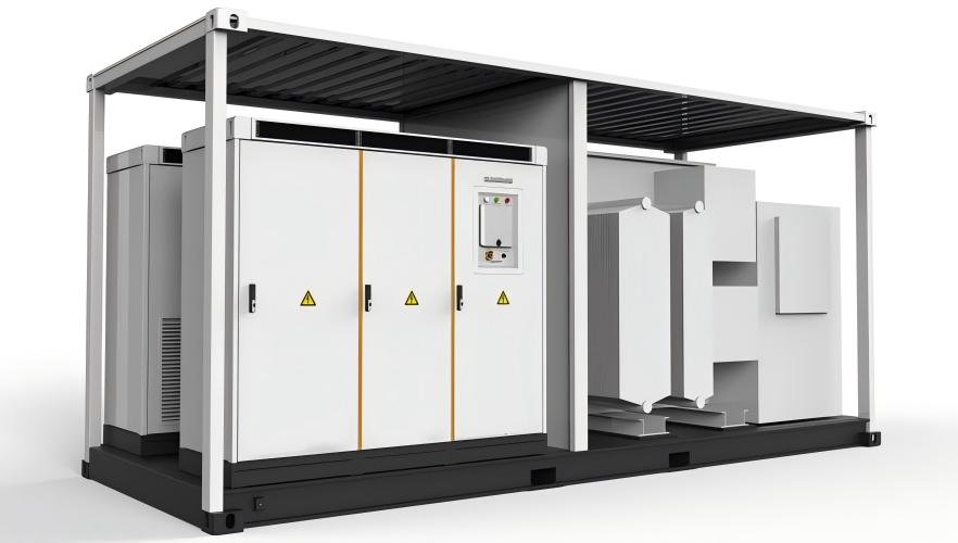
As the global transition toward renewable energy accelerates, energy storage systems (ESS) have become a critical component in stabilizing power grids and enabling efficient energy utilization. From residential battery packs to utility-scale storage containers, thermal management remains one of the most decisive factors affecting system safety, performance, and longevity.
From an engineering standpoint, establishing a reliable and efficient thermal pathway under varying operating conditions is essential. Among various thermal interface materials, the thermal pad stands out due to its flexibility, electrical insulation, and ease of integration. In modern ESS design, a high-performance thermal interface pad is no longer optional—it is fundamental.
Key Thermal Challenges in Energy Storage Systems
During operation, heat is primarily generated from the following components:
- Battery cells
- Battery Management Systems (BMS)
- Power conversion systems (IGBTs, MOSFETs)
- DC/DC converters and inverters
- Busbars and electrical connectors
Under high charge/discharge rates and continuous cycling, heat accumulation can lead to several critical issues:
- Cell imbalance caused by temperature gradients
- Accelerated aging of electronic components
- Reduced system efficiency
- Potential thermal runaway risks
To mitigate these risks, minimizing interfacial thermal resistance is essential. This is where a properly selected thermal pad plays a crucial role.
Typical Applications of Thermal Pad in ESS Design
1. Between Battery Cells and Cooling Plates
Microscopic surface irregularities often prevent direct contact between battery modules and cooling plates. A compliant thermal interface pad fills these gaps, significantly improving heat transfer efficiency.
2. BMS PCB to Enclosure
Thermal pads are used to transfer heat from BMS components to the metal housing, enabling passive heat dissipation while maintaining electrical insulation.
3. Power Modules to Heat Sinks
Power devices require materials that offer both high thermal conductivity and dielectric strength. A silicone-based thermal pad ensures consistent thermal coupling and operational safety.
4. Busbars and Connector Interfaces
Localized heating at high-current connection points can be mitigated with targeted use of thermal interface pads, improving system reliability.
Engineering Considerations for Thermal Pad Selection
Selecting the appropriate thermal pad requires careful evaluation of the following parameters:
Thermal Conductivity
Typically ranging from 1.0 to 12.0 W/m·K. For energy storage applications, materials with ≥5.0 W/m·K are recommended.
Thickness and Compressibility
Available in thicknesses from 0.5 mm to 5.0 mm. Adequate compressibility ensures proper gap filling without excessive mechanical stress.
Hardness
A balanced hardness level is required to maintain both conformity and structural integrity.
Electrical Insulation
Volume resistivity should exceed 10¹² Ω·cm to meet safety standards.
Operating Temperature Range
A reliable thermal pad should perform consistently between -40°C and 150°C or higher.
Recommended Solution: SF500 Silicone Thermal Pad
In practical ESS deployments, material consistency and reliability are key. One proven solution is the SF500 Silicone Thermal Pad, which has demonstrated stable performance across various energy storage applications.
Key Specifications:
- Thermal Conductivity: 5.0 W/m·K
- Thickness Range: 0.5 mm – 5.0 mm (customizable)
- Operating Temperature: -40°C to 200°C
- Electrical Insulation: उत्कृष्ट dielectric strength
- Material Type: Silicone-based thermal interface pad
Engineering Advantages:
- Superior Gap Filling: Effectively reduces contact resistance between uneven surfaces.
- Long-Term Stability: Maintains performance under thermal cycling and harsh environments.
- Manufacturing Flexibility: Supports die-cutting and adhesive backing for efficient assembly.
- Enhanced Safety: High dielectric strength ensures electrical isolation.
In field applications, integrating this thermal pad between battery modules and cooling plates has been shown to reduce temperature differentials by approximately 15–20%, significantly improving thermal uniformity.
Best Practices for Thermal Pad Integration
Optimize Thickness Selection
Avoid excessive thickness, which increases thermal resistance, while ensuring sufficient gap coverage.
Control Compression Ratio
A compression range of 10%–30% is typically optimal for performance and durability.
Ensure Surface Quality
Flat and smooth contact surfaces maximize the effectiveness of the thermal interface pad.
Integrate with System-Level Cooling
Thermal pads should be part of a comprehensive strategy including heat sinks, airflow, or liquid cooling.
Conclusion
As energy storage systems continue to evolve toward higher energy density and stricter safety requirements, thermal management design becomes increasingly critical. The thermal pad, as a key interface material, plays an essential role in ensuring efficient heat transfer and system reliability.
By selecting high-performance solutions such as the SF500 Silicone Thermal Pad and applying sound engineering practices, designers can significantly enhance thermal performance, extend system lifespan, and improve operational safety.
For engineers working in ESS design, a deeper understanding of thermal interface pad characteristics and applications is fundamental to building robust and future-ready systems.
Thermal Pad Solutions for Rail Transit Thermal Management Systems
Thermal Pad Solutions for Electric Vehicle Thermal Management
Related Article