
Thermal Pad Selection Guide: Thickness and Compression Rate Explained
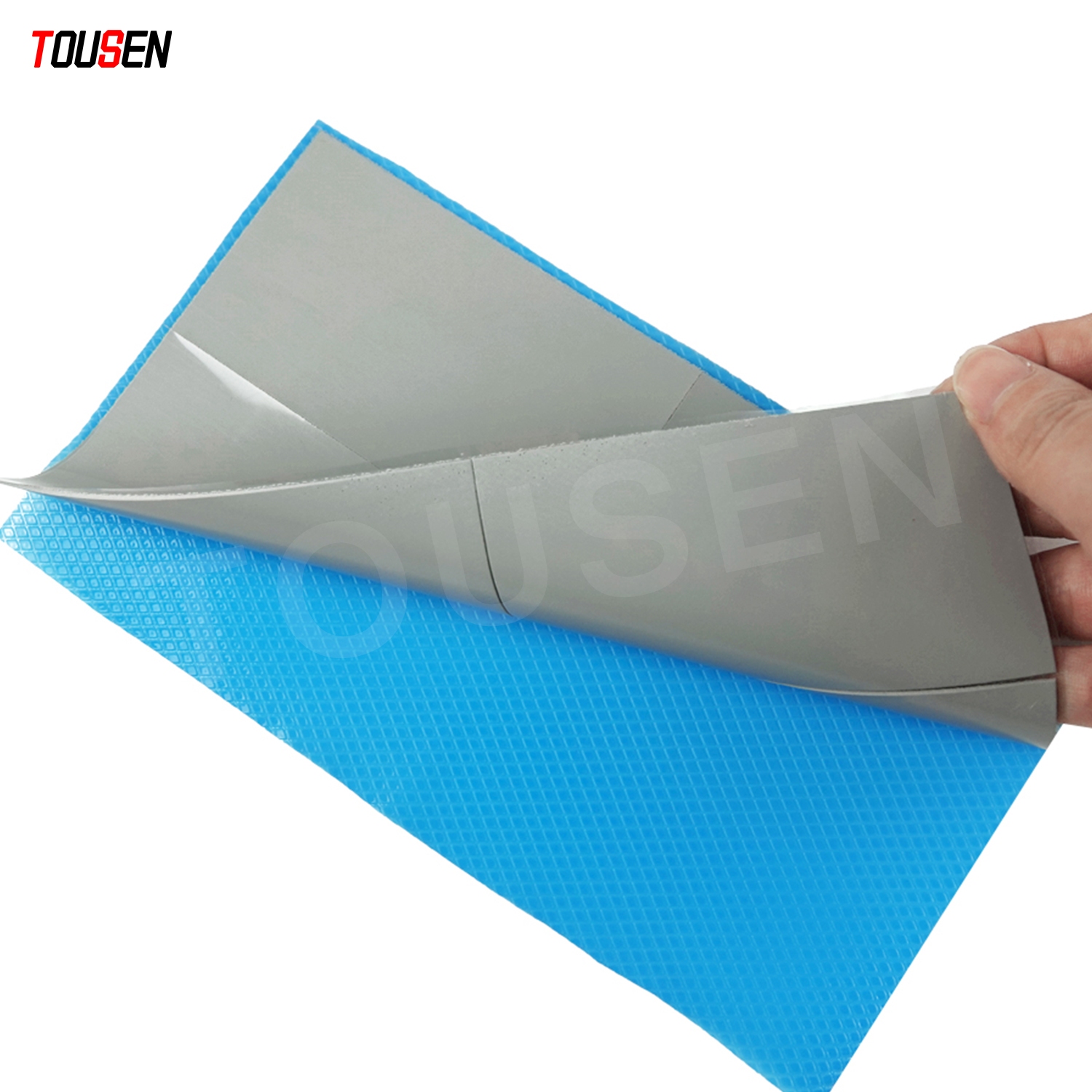
Thermal Pad Selection Guide: Thickness and Compression Rate from an Engineer’s Perspective
Thermal interface materials (TIMs) play a critical role in modern electronic thermal management. Among them, silicone thermal pads are widely used due to their gap-filling capability, electrical insulation, and ease of assembly. This article provides a professional and engineering-focused analysis of thermal pad parameters, with particular emphasis on thickness and compression rate, offering practical selection guidance for product designers and thermal engineers.
Why Thickness and Compression Rate Are the Core Selection Parameters
The primary function of a thermal pad is to fill macroscopic gaps between heat-generating components (such as ICs, power devices, or memory modules) and heat sinks or chassis surfaces. In real-world assemblies, surface flatness, component tolerances, and mechanical stack-up make direct metal-to-metal contact impractical.
Thickness determines whether the thermal pad can fully bridge the gap without overstressing components, while compression rate determines how effectively the pad conforms to surface irregularities under a given assembly force. These two parameters directly affect contact area, interface thermal resistance, and long-term mechanical reliability.
Key Thermal Pad Parameters Explained
1. Thermal Conductivity and Thermal Resistance
Thermal conductivity (W/m·K) represents the intrinsic heat conduction capability of the material. However, from an engineering perspective, thermal resistance is often the more meaningful metric, as it incorporates material thickness, contact pressure, and surface roughness.
For pads of identical thermal conductivity, increasing thickness will linearly increase thermal resistance. Therefore, laboratory or application-specific thermal resistance testing under realistic compression conditions is strongly recommended.
2. Thickness and Tolerance Management
Common thermal pad thicknesses range from 0.1 mm up to 5 mm or more for special applications. Thickness selection should be based on the maximum gap within the tolerance stack-up, while allowing an appropriate compression margin—typically 10% to 30%.
Engineers should also consider dimensional tolerances and edge effects. Pads should be slightly smaller than the mating surface to prevent edge extrusion and to facilitate controlled compression.
3. Compression Rate, Elastic Recovery, and Long-Term Stability
Compression rate describes the percentage reduction in thickness under assembly load. Typical recommended compression ratios range from 20% to 50%, depending on material formulation and application.
Long-term performance depends heavily on resistance to compression set and creep, especially in high-temperature or long-life products. Excessively soft materials may accommodate tolerances initially but can suffer permanent deformation over time, leading to increased thermal resistance.
4. Hardness (Shore A)
Thermal pad hardness typically ranges from 20 to 70 Shore A. Softer pads improve surface conformity but may be prone to extrusion or long-term deformation, while harder pads provide better mechanical stability at the cost of reduced compliance.
In many designs, a mid-range hardness (approximately 30–50 Shore A) offers an optimal balance between thermal performance and mechanical reliability.
5. Filler Materials and Electrical Properties
Silicone thermal pads achieve high thermal conductivity through ceramic fillers such as aluminum oxide, boron nitride, or aluminum nitride. These fillers generally maintain electrical insulation, which is essential for applications involving exposed conductors or solder joints.
Engineers should verify that the selected pad is non-conductive, non-corrosive, and chemically compatible with copper, aluminum, and PCB materials.
6. Thermal Stability and Environmental Reliability
Standard silicone thermal pads typically operate from -50 °C to +150 °C, with specialized formulations supporting higher temperatures. Thermal cycling, humidity, and vibration can all affect long-term performance.
For demanding environments such as automotive, industrial, or telecom equipment, validation data for thermal cycling, damp heat, and aging should be reviewed during material selection.
Recommended Engineering Selection Process
- Define thermal targets, power dissipation, allowable temperature rise, and service life.
- Measure or calculate maximum gap and tolerance stack-up.
- Preselect materials based on thermal conductivity, insulation requirements, and temperature rating.
- Select nominal thickness based on gap minus target compression.
- Verify compression force, extrusion risk, and mechanical fit.
- Validate thermal resistance under real assembly pressure.
- Conduct environmental and reliability testing before mass production.
Typical Application Scenarios
- Consumer Electronics: Thin pads (0.2–1.0 mm), moderate compression, low compression set.
- Power Electronics: Higher thermal conductivity, controlled hardness, enhanced creep resistance.
- Automotive Systems: High-temperature stability, proven thermal cycling and humidity resistance.
Common Design Pitfalls
A frequent mistake is focusing solely on thermal conductivity while neglecting thickness, compression behavior, and long-term stability. Another common issue is selecting overly soft materials without evaluating compression set or creep. A holistic evaluation of thermal, mechanical, and environmental factors is essential.
Thermal Pad Solutions from ITOUSEN
ITOUSEN offers a comprehensive range of silicone thermal pads designed to meet diverse thermal management requirements across consumer, industrial, and automotive applications. These materials are engineered for optimized thickness tolerance, controlled compression behavior, reliable thermal performance, and long-term stability.
For detailed specifications and available options, please visit the ITOUSEN Thermal Pad Product Category, where engineers can explore different thermal conductivity levels, thickness ranges, and application-specific solutions.
Conclusion
Effective thermal pad selection requires more than comparing datasheet conductivity values. From an engineering standpoint, thickness, compression rate, hardness, and long-term reliability must be evaluated together to minimize thermal resistance and ensure stable performance over product lifetime. Early-stage validation combining mechanical fit, thermal testing, and environmental stress screening significantly reduces design risk and improves system reliability.
ASUS RTX 2080 Turbo Thermal Pads Replacement Guide
Why Thermal Pads of the Same Thickness Perform Differently | Engineering FAQ
Related Article