Thermoelectric Cooler Thermal Management with Silicone Thermal Pads
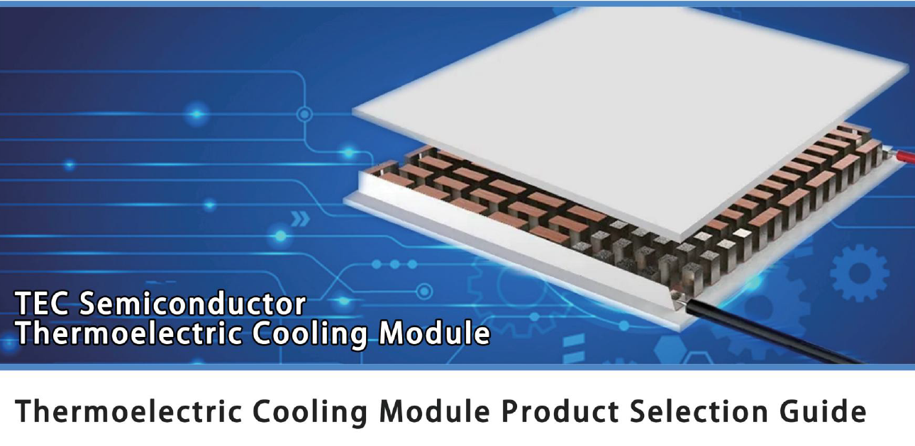
Silicone Thermal Pads in Thermoelectric Cooling: Solving the Hot Side Heat Flux Problem
A Peltier module is a heat pump with an honest but unforgiving balance sheet. A 40 x 40 mm module pumping 60 W at near zero temperature difference draws about 100 W of electrical power, so 160 W must leave the hot ceramic into a heatsink whose contact area is only 16 cm2. That is close to 10 W/cm2, an order of magnitude above the flux of a switching device on the same board. It is also why thermoelectric cooler thermal management fails at the interface far more often than at the fins: when the layer between module and heatsink is a silicone thermal pad, its thickness sets the hot-side temperature, and that temperature sets how much cooling the module can deliver at all.
Where a Peltier stack spends its temperature budget
Two interfaces matter, and both are usually under-specified in the first prototype. The cold side carries only the pumped heat; the hot side carries the pumped heat plus the input power, so one thermal interface material cannot be specified for both.
| Interface | Heat flux | Budget | Decisive property |
|---|---|---|---|
| Object to cold plate (sensor, cuvette, laser diode) | 2–6 W/cm2 | < 1.0 K | Thin, low modulus, full wetting at 5–10 psi |
| Cold plate to TEC cold ceramic | 2–6 W/cm2 | < 1.0 K | 0.3–0.5 mm, no grease pump-out under cycling |
| TEC hot ceramic to heatsink | 8–12 W/cm2 | < 2.0 K | Thinnest section at 8–15 W/m·K |
| Frame, edge and sealing surfaces | < 1 W/cm2 | not thermal | Dielectric strength, low water uptake |
| Driver board, output capacitors | 0.5–2 W/cm2 | < 5 K | Softness at low clamp pressure |
The arithmetic that decides pad thickness
Resistance scales with thickness and inversely with conductivity, and at Peltier-level flux that linearity becomes expensive. Counting the bulk drop alone, a 1.0 mm layer at 3.0 W/m·K contributes about 33 K at 10 W/cm2 before any contact term. The same 6 K budget is met by 0.5 mm at 8.0 W/m·K or 0.8 mm at 12.0 W/m·K, a calculation most thermoelectric design reviews never run.
| Bulk drop at 10 W/cm2 | 3.0 W/m·K | 8.0 W/m·K | 12.0 W/m·K |
|---|---|---|---|
| 0.3 mm | 10.0 K | not offered* | not offered* |
| 0.5 mm | 16.7 K | 6.3 K | 4.2 K |
| 0.8 mm | 26.7 K | 10.0 K | 6.7 K |
| 1.0 mm | 33.3 K | 12.5 K | 8.3 K |
How one extra kelvin becomes lost cooling capacity
Cooling capacity falls as the temperature difference across the module rises, and the slope is steep near the top of the curve: a 50 W module at half load typically loses 3 to 5 percent of Qc per additional kelvin on the hot side. Two kelvin of avoidable interface rise therefore costs 6 to 10 percent of the cooling the customer paid for, and it costs it silently, because the heatsink still feels warm to the touch.
There is a worse loop. A hotter hot side forces a higher current to hold the cold-side temperature, the current adds Joule heat inside the module, and the extra heat raises the hot side again. Most standard modules are rated for an 80 °C hot side, so every kelvin spent in a thermal interface material comes straight out of the margin against this spiral.
Five constraints a Peltier stack adds
Clamp pressure on brittle ceramic. Alumina and aluminium nitride substrates tolerate 5 to 20 psi in normal mounting and dislike point loads far more than pressure itself. A 40 Shore 00 silicone thermal pad conforms at that pressure; a hard pad demands force the ceramic cannot take.
Expansion mismatch under cycling. An aluminium heatsink moves differently from a ceramic substrate, and a chiller switching thousands of times delivers that difference to the interface as shear. Compression set, not conductivity, decides end-of-life resistance here.
Condensation. A cold side held below the dew point wets every surface in the stack. Closed-cell silicone with low water uptake keeps its dielectric strength, whereas a hygroscopic gap filler can lose insulation resistance by orders of magnitude after one humid season.
Optical and sensor contamination. Thermoelectric cooling often surrounds laser diodes, image sensors and analytical instruments, where low-molecular siloxane from a poorly specified pad fogs a window nobody can clean. Specify oil bleed below 1 percent after 24 h at 150 °C.
Continuous heat at moderate temperature. The hot side sits at 60 to 80 °C for years rather than at 150 °C for minutes, exactly the regime where creep and compression set accumulate without visible sign.
Matching the grade to each interface
The SF Series from TOUSEN covers 1.5–15.0 W/m·K in 0.3–10.0 mm sections at Shore 00 hardness of 40 or 60, with 0.1 mm die-cut tolerance and a 200 x 300 mm standard sheet. In a Peltier stack, thermoelectric cooler thermal management reduces to matching three thicknesses to three measured gaps, not to picking the highest number in the catalogue.
| Grade | W/m·K | Impedance, 1 mm @ 30 psi (°C·in2/W) | Thickness range | Typical position in a TEC stack |
|---|---|---|---|---|
| SF100 | 1.5 | 0.90 | 0.3–10.0 mm | Driver board, sensor PCB, frame |
| SF400 | 2.5 | 0.50 | 0.3–10.0 mm | Cold-side plate at 0.3–0.5 mm |
| SF500 | 3.0 | 0.45 | 0.3–10.0 mm | Low-flux cold side, cuvette mount |
| SF600G | 6.0 | 0.30 | 0.5–5.0 mm | Hot side of a 30–60 W module |
| SF800 | 8.0 | 0.22 | 0.5–5.0 mm | Hot side at 8–10 W/cm2 |
| SF1000 | 10.0 | 0.18 | 1.0–5.0 mm | Hot side with a generous gap |
| SF1200 | 12.0 | 0.15 | 0.8–5.0 mm | Compact high-flux hot side |
| SF1500 | 15.0 | 0.10 | 1.0–5.0 mm | Highest flux, gap above 1 mm |
Hot side
On a 40 x 40 mm module this is where money is spent and mistakes are made. A 0.5 mm silicone thermal pad at 8.0 W/m·K is the usual optimum for 8–10 W/cm2 at 10–20 psi; 12.0 W/m·K pays off only when the gap is already held to 0.8 mm, and a 1.0 mm section at any grade signals a housing that was never toleranced.
Cold side
Cold-side flux is lower because it carries only the pumped load, so a thermal interface material of 2.5–3.0 W/m·K at 0.3–0.5 mm is sufficient, and its softness protects a delicate cold plate or a direct-bonded sensor. A 12.0 W/m·K grade adds cost without measurable benefit, and a stiffer pad can lift the plate off the module.
Qualification that reflects how the product is used
Measure impedance to ASTM D5470 at 10, 20 and 30 psi, not at 30 psi alone, because a Peltier stack rarely reaches catalogue pressure. Repeat after 5,000 power cycles and after 1,000 h of damp heat at 85 °C / 85 % RH with the stack assembled: condensation happens inside the product, not in a sample holder. Verify insulation resistance at 500 V wet and dielectric strength at the thinnest die-cut section. Compression set to ASTM D395 B at 70 °C represents the hot side better than the 125 °C used for automotive parts, and the thermal interface material should also be checked for oil bleed and outgassing wherever optics share the enclosure.
Assembly and service notes
- Die-cut with a 0.1 mm tolerance and a carrier film; hand-cut parts vary by more than the whole compression window of a TEC stack.
- Load through a compliant plate or spring frame, never on the ceramic edge; 10 psi distributed beats 20 psi concentrated.
- Keep the release liner until placement and never re-seat a pad that has touched a surface.
- Never reuse a silicone thermal pad after teardown: compression set is permanent and the reused layer reads several kelvin worse.
- Store at 10–30 °C away from UV and dust; 24-month shelf life, shorter once the bag is open.
Conclusion
Thermoelectric cooling is limited by the temperature difference a module can sustain, and thermoelectric cooler thermal management is largely the art of not spending that difference in a gap. Size the heatsink for pumped load plus input power, size the pad from the measured gap and the real clamp pressure, and check the loss in kelvin before choosing a grade by conductivity alone. A correctly specified silicone thermal pad then does two jobs in one layer: it keeps the hot ceramic cool enough for the module to hold rated capacity, and it absorbs the mechanical mismatch that would otherwise crack a substrate over a product lifetime.
Full parameters, thickness ranges and die-cut capability of the thermal interface material referenced above are listed on the SF Series silicone thermal pad product page, where gap samples can be requested for a Peltier stack of your own dimensions.
Automotive Power Module Thermal Management with Silicone Thermal Pads
Related Article