Automotive Power Module Thermal Management with Silicone Thermal Pads
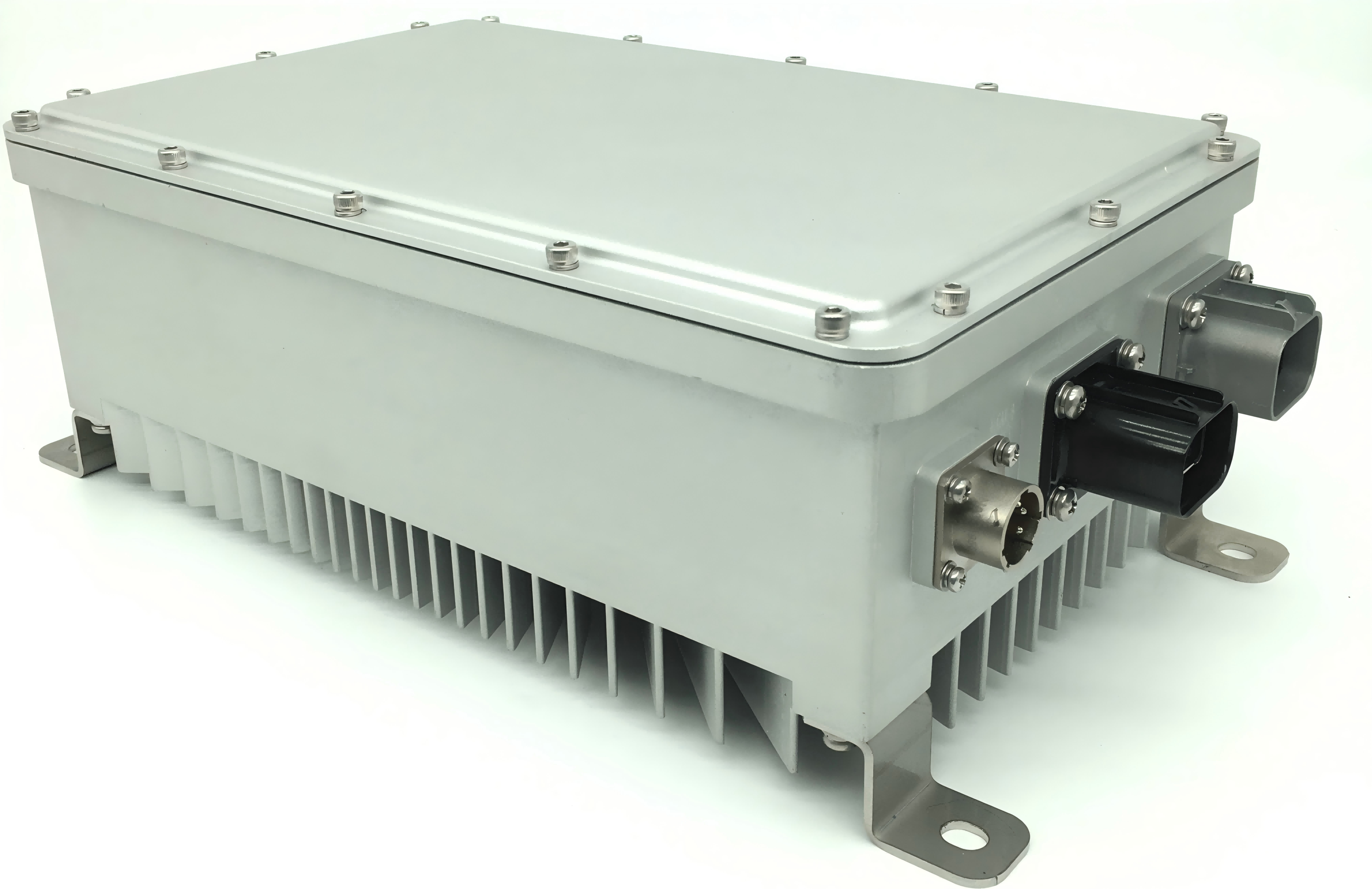
Thermal Interface Design for Automotive Power Modules: Silicone Thermal Pads in Onboard Chargers and DC-DC Converters
An onboard charger is one of the least forgiving thermal environments in a vehicle. An 11 kW three-phase unit running at 97 % efficiency still dissipates roughly 340 W inside a die-cast housing that must fit under the floor, survive an under-hood ambient of 105 °C, and last fifteen years or 250,000 km without service. The coolant loop may sit at 65–85 °C, the SiC junction is limited to 175 °C, and the mounting plane is a casting rather than a machined block. In this budget the layer between the power module and its cold plate carries a disproportionate share of the risk: the thermal interface material. Where that layer is a silicone thermal pad, its compressed thickness, compression set and dielectric margin decide whether the converter holds full power on a 45 °C summer climb.
Where the heat is generated in an automotive power module
Losses in an OBC plus DC-DC assembly are distributed across five interfaces, and each has a different gap, pressure and reliability demand.
| Heat source | Share of loss | Limiting temperature | Typical gap | Decisive pad property |
|---|---|---|---|---|
| SiC or IGBT module to cold plate | 45–55 % | 150–175 °C junction | 0.3–1.0 mm | Impedance at 10–30 psi clamp |
| Transformer, resonant inductor | 20–25 % | 130–155 °C winding | 1.0–3.0 mm | Thick-section forming, low oil bleed |
| DC-link and snubber film capacitors | 8–12 % | 105 °C case | 0.5–2.0 mm | Softness at low pressure |
| Gate driver and control board | 5–8 % | 105–125 °C | 0.3–0.8 mm | Low modulus, reworkable |
| Busbars, terminals, EMI filter | 5–10 % | 120–130 °C | 0.3–1.5 mm | Dielectric strength, flame rating |
The four constraints that automotive adds
Temperature swing. A silicone thermal pad that is fine in a laboratory chamber at a constant 85 °C may harden after 1,000 power cycles between −40 °C and 125 °C. Compression set is the mechanism: the material takes a permanent deformation, contact area falls, and impedance rises exactly when the module is hottest.
Vibration and shock. ISO 16750-3 profiles apply random vibration in three axes with accelerations that a bolted stack can pass but a poorly fixtured pad cannot. Thick, soft sections need a carrier film and a die-cut that stays in place during pick-and-place.
800 V isolation. With an 800 V bus, the pad is the primary insulation between a live module and a grounded cold plate, so dielectric strength is a safety function rather than a datasheet line. It must hold at the thinnest point of the die-cut, after thermal ageing and damp heat.
Assembly pressure limits. Automotive housings are die-cast aluminium or engineering plastics, and the module clamp is often limited to 10–25 psi to protect the ceramic substrate and the plastic frame. A low-modulus pad at 40 Shore 00 conforms at that pressure, while a hard pad needs pressure the housing cannot take.
Gap tolerance in a die-cast housing
Die-cast flatness contributes 0.10–0.30 mm across a 150 mm pocket, machining of the cooling channel another 0.05 mm, module substrate camber 0.05–0.10 mm, and coating adds 0.02–0.05 mm. A nominal 0.50 mm gap is therefore 0.35–0.85 mm in production, and a nominal-thickness silicone thermal pad either leaves an air layer at the loose end or over-compresses at the tight end. The working rule for any thermal interface material is 0.85–0.90 of the maximum gap: at least 10 % compression everywhere, below 30 % everywhere, and never a pad specified by free thickness alone.
Parameters that predict field behaviour
Automotive power module thermal management rarely fails at the heatsink; it fails in the interface, which is why six numbers decide the design more than any headline conductivity rating.
- Impedance at 10, 20 and 30 psi. Automotive clamps rarely reach the 30 psi of a standard datasheet; ask for the curve, not the headline conductivity.
- Compression set after 22 h at 125 °C. This is the single most useful predictor of end-of-life impedance in a power module.
- Dielectric strength after ageing. 5 kV/mm minimum at the thinnest section, verified after 1,000 h at 125 °C and damp heat.
- Oil bleed and siloxane volatility. Low-molecular siloxane can fog a connector or a sensor window; specify bleed below 1 % after 24 h at 150 °C.
- Flame and material compliance. UL94 V-0, RoHS, halogen-free and REACH, with IMDS entry for the OEM material data system.
- Operating range. −50 °C to 200 °C covers cold-crank and near-cold-plate excursions with margin; 24-month shelf life keeps reels usable across a model-year build.
Matching the grade to the position
The SF Series from TOUSEN spans 1.5–15.0 W/m·K in 0.3–10.0 mm sections with Shore 00 hardness of 40 or 60 and die-cut capability at 0.1 mm tolerance. Across an OBC, a DC-DC and the auxiliary board, automotive power module thermal management really comes down to three gaps, and one approved family can cover all of them.
| Grade | W/m·K | Impedance, 1 mm @ 30 psi (°C·in²/W) | Thickness | Typical automotive location |
|---|---|---|---|---|
| SF100 | 1.5 | 0.90 | 0.3–10.0 mm | Gate driver board, sensor PCB |
| SF400 | 2.5 | 0.50 | 0.3–10.0 mm | DC-link capacitors, EMI filter |
| SF500 | 3.0 | 0.45 | 0.3–10.0 mm | Transformer and inductor clamping |
| SF600G | 6.0 | 0.30 | 0.5–5.0 mm | IGBT module to cold plate |
| SF800 | 8.0 | 0.22 | 0.5–5.0 mm | SiC module, 400/800 V traction |
| SF1200 | 12.0 | 0.15 | 0.8–5.0 mm | High-density 800 V OBC stage |
Power module to cold plate
For a 0.3–1.0 mm gap at 20–30 psi, a 6–8 W/m·K pad at 40 Shore 00 gives the lowest total resistance while keeping point loads off the substrate. Above 8 W/m·K the gain per step flattens, and the cost is better spent on casting flatness or a thinner gap than on another conductivity grade.
Magnetics and capacitors
The transformer and resonant inductor are large, low-pressure interfaces where 2.5–3.0 W/m·K material in 1.0–3.0 mm sections fills the curvature of a wound component and the housing without loading the terminals, and doubles as a vibration damper. Film capacitors, with a 105 °C case limit and a modest loss, need softness more than conductivity.
800 V and dual-side cooling
Dual-side-cooled modules place a silicone thermal pad on both faces of the die, so thickness symmetry matters more than a single grade step: an asymmetric stack shifts the die temperature gradient and unbalances the parallel switches. Die-cut parts with a 0.2 mm edge margin and carrier film keep the installed thickness identical on both sides.
Qualification plan to write into the drawing
Thermal impedance to ASTM D5470 at three pressures, then the same measurement after 1,000 thermal cycles from −40 °C to 125 °C and after 1,000 h of damp heat at 85 °C / 85 % RH. Compression set to ASTM D395 B at 125 °C. Dielectric strength and insulation resistance after ageing, at the thinnest die-cut section. Vibration to ISO 16750-3 and a mechanical shock sweep on the assembled module. Oil bleed gravimetrically at 150 °C, and outgassing on any unit that shares an enclosure with optical or sensing components. Production parts should come from an IATF 16949 line with PPAP documentation, because the thermal interface material is the one layer that cannot be inspected after the module is bolted down.
Assembly and service notes
- Die-cut with 0.1 mm tolerance and a carrier film; hand-cut pads vary by more than the entire compression window.
- Keep the release liner on until the silicone thermal pad is placed, and never re-place a pad that has touched a surface.
- Tighten in a cross pattern in two stages, then confirm compression on the first unit of each lot.
- Never reuse a pad after teardown: compression set is permanent, and the second installation has neither thickness nor wetting.
- Store at 10–30 °C away from UV; 24-month shelf life, shorter once the bag is open.
Conclusion
Automotive power module thermal management is a chain of series resistances, and the interface is the link that is cheapest to change and most expensive to get wrong. Specify the gap from measured castings, the impedance at the pressure the housing actually applies, and the dielectric and flame performance the OEM will audit. A correctly sized silicone thermal pad then works as a mechanical part as much as a thermal one: it absorbs casting tolerance, damps vibration, insulates an 800 V module and keeps its impedance through fifteen winters.
Full parameters, thickness options and die-cut capability of the thermal interface material described here are listed on the SF Series silicone thermal pad product page, where samples can be requested for gap and clamp-pressure validation on your own housing.
Thermoelectric Cooler Thermal Management with Silicone Thermal Pads
Silicone Thermal Pad Selection for PV Inverter Thermal Management
Related Article